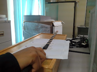
The design was almost same as the first design but now we cut the popsicle sticks with the length as the spacing between the elements. All the elements was attached to the popsicle sticks and tape with black tape.
After finish attached the elements to the popsicle sticks, then we attached another layer of sticks to support the antenna.
The SMA connector that soldered into the coaxial cable and another end of coaxial cable solder to the radiator of antenna.
First, we do a measurement of antenna which is made by use suitable dimension for radiator, reflector and director. Table shown the measurement that we use as our reference.
|
Elements
|
1
|
2
|
3
|
4
|
5
|
6
|
7
|
8
|
9
|
10
|
11
|
12
|
13
|
14
|
15
|
|
Length (cm)
|
6.1
|
6.0
|
5.4
|
5.3
|
5.2
|
5.2
|
5.1
|
5.1
|
5.0
|
5.0
|
5.0
|
4.9
|
4.9
|
4.9
|
4.8
|
Then, the paper clips were straight up. Paper clip should be really straight to avoid any
errors!
For the antenna backbone, the popsicle stick was measured equally for each sticks to cut off the curve in the end of stick
After measured
the sticks, marked the area to be discard. Then cut the unwanted region of the
sticks.
The
paper clip that already straightened up was measured as the table requirement
for this antenna. The clip was cut according to length of the elements.
The distance between elements were measured and marked before attached all the elements on the backbone.
The SMA connector was soldered to the coaxial cable and we also solder the coaxial cable with the feed or radiator of the antenna.
The Driven Element (dipole) length, F should around 0.5λ (half wavelength)
The Reflector length, R should longer than dipole approximately
5%
The Directors, Dn should shorther than dipole approximately
5%
The spacing between Reflector and DE, SR
in range of 0.1 to 0.35 λ
The spacing between Directors, SD in
range of 0.1 to 0.5 λ or more
Impedance at cable feed-point is decreasing
due to the effect of additional parasitic element (Reflector and Directors) and
their spacing. This problem can be overcomed by the folded dipole (Driven Element). As the dipole length, F is half of
the wavelength, and then the impedance will be increase 4 times about 300Ω.
Subscribe to:
Comments (Atom)
1 followers
1 subscribers
Popular Posts
-
 Basic Design Parameter of Yagi Uda Antenna
-
 Result of first attempt
-
 Basic Introduction to Yagi-Uda Antenna
-
 discussion session with our lecture- madam ALYANI
-
 Power Dipole Organisation Chart
-
 In the making of Yagi Uda
-
 Antenna Cable and Connector
-
 Second Attempt! In the making of Yagi Uda
-
 antenna materials video introduction
-
 Mission Complete! Result 2.4GHz achieved


